Recommended products

Perfect Packaging

Attention to detail

High Quality Sound

Attention to detail

Fast Delivery

Great value enjoyment

Personalization

First-class quality

Global Sales

Reasonable Price

e

Why Choose Hyper?

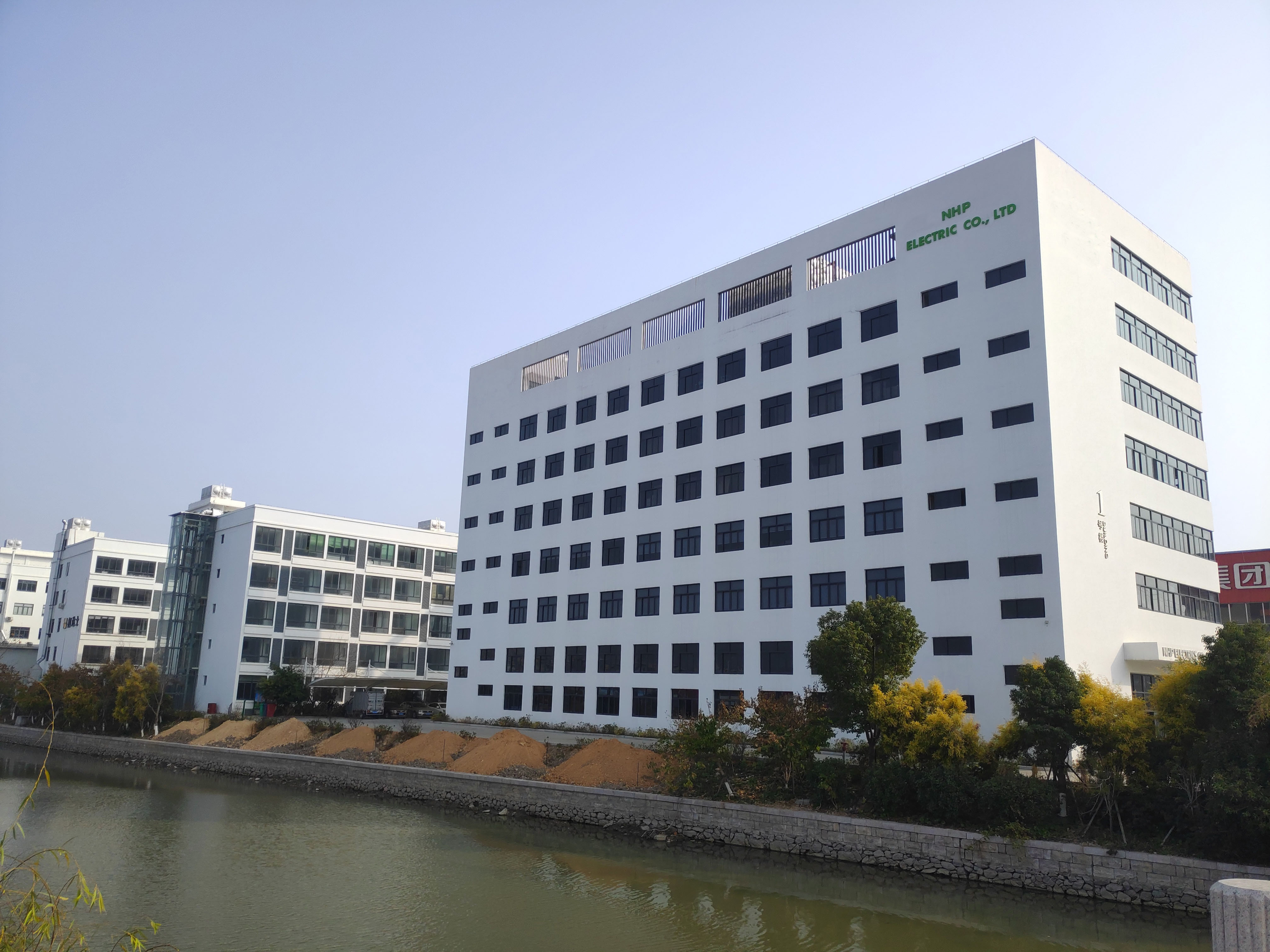
Zhejiang HYPER Electrical Co., Ltd. / NHP Electric Co., Limited specializes in designing and manufacturing critical components and customized technology solutions.

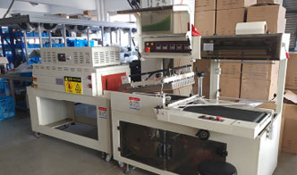
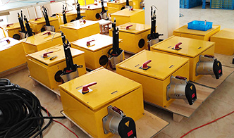
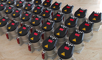
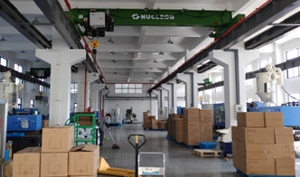
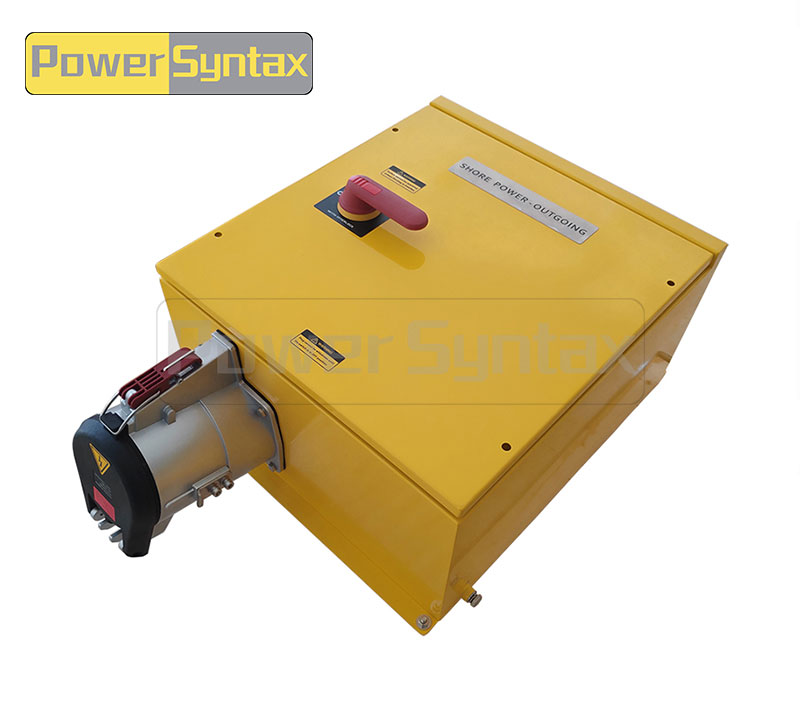
HYPER we operate a 10,000m² factory with 500 workers, capable of producing over 100,000 distribution boxes and 80,000 industrial plugs and sockets monthly. We invest $150,000 annually in new product development and use our own injection machines to ensure high-quality plastic components.

View More >

Factory display

View More >
NEWS CENTER
Why Does My Shore Power High Current Plug Overheat During Dock Operations

29

2026-05

Why Does My Shore Power High Current Plug Overheat During Dock Operations

You‘re running a vessel at the dock—cranes loading, HVAC running, galley in full operation. Then you notice the shore power connection is too hot. Not the cable, but the Shore Power High Current Plug itself, warm to the touch at first, then too hot to handle. Overheating shore power connectors are the single most common failure mode in dock operations worldwide, and they rarely fix themselves. Left unchecked, a hot plug melts insulation, carbonizes contacts, and can start a fire. But before you condemn the entire system, look closely at where the heat is coming from. The location of the heat—the pin area, the cable entry, or the whole housing—tells you exactly what’s wrong and what to fix.


Heat coming from the pin and sleeve area 

If the plug feels hottest around the mating face where pins enter the socket, the problem is at the electrical contact interface.

Insufficient contact pressure after repeated mating cycles. Every time you connect and disconnect a high-current plug, the spring tension in the socket contacts relaxes slightly. After hundreds of cycles, the contact pressure drops below the threshold needed for a stable, low-resistance connection. The result is a higher resistance path; current still flows, but the contact generates heat instead of carrying the load cleanly. If the plug inserts or removes with noticeably less friction than a known-good unit, the contacts are worn.

Oxidation build-up on pin surfaces reducing conductivity. In marine environments, silver-plated or copper alloy pins develop a dark oxide layer over time. Oxidation acts as an insulator, increasing contact resistance and generating heat. What looks like a “little discoloration” can be enough to cause severe overheating under full load. If the pins appear dark, dull, or show black spotting, clean them with a fine abrasive pad (not sandpaper) and apply a thin film of dielectric grease.

Debris or sand ingress in the socket barrel. Dust, sand, and salt crystals accumulate inside the socket barrel, physically interfering with full pin insertion. Even a partial insertion prevents the contacts from seating correctly, creating a high-resistance interface. If the plug does not fully seat with a positive detent, or the locking mechanism engages earlier than expected, debris is likely.


Heat concentrated at the cable entry point 

If the plug body is cool near the mating face but hot where the cable enters, the problem is inside the termination.

Undersized cable gauge relative to current draw. A cable that is too small for the load heats up along its entire length. That heat conducts into the plug body through the terminal connection. If the cable feels warm beyond the plug, not just at the entry point, the gauge may be undersized. For a 300A continuous load, 70mm² copper is the minimum; for 400A, 95mm² to 120mm², depending on cable rating and insulation type. The higher the current, the greater the heat gradient between undersized and properly sized cable.

Loose screw termination inside the plug body. Even properly sized cable will overheat at the termination if the terminal screw is not torqued correctly. The connection point vibrates loose over time from ship movement and thermal cycling. A loose termination has a fraction of the contact area it should, creating a concentrated hot spot that can melt the plug body from the inside out. If the cable pulls out with light force when the screw is supposedly tight, or the screw turns with less resistance than expected, the termination needs attention. An infrared thermometer pointed at the cable entry will show significantly higher temperature there than elsewhere on the plug.

Damaged conductor strands from improper stripping. When a cable is stripped for termination, nicked strands are easily missed. Under load, the reduced cross-section at that point becomes a localized hot spot. Over time, the damaged strands heat up, oxidize, and eventually break, reducing the conductor further in a cascading failure. If several strands are visibly cut where the conductor enters the terminal, the cable end requires re-stripping.


Heat spreading across the entire plug housing 

When the whole plug body runs hot—without a clear hotspot at pins or cable entry—the cause is usually external to the termination itself.

Ambient temperature exceeding the plug‘s design limit. Shore power connectors exposed to direct sunlight on a steel dock can easily reach internal temperatures of 60–70°C before any current flows. Add 200A of load, and the total temperature may exceed the insulation rating. This is particularly common in summer in tropical ports where ambient temperatures regularly exceed 40°C. If the plug runs hot even on cool days, ambient is likely not the primary cause; but if the problem appears seasonally or only on sunny afternoons, solar loading is a major contributor.

Continuous operation at 100% rated current without cooling interval. Even properly designed connectors have thermal time constants. Running at full rated current for hours without a period of reduced load may cause the plug to exceed its steady-state temperature limit. The plug’s rating assumes a certain duty cycle; continuous full-load operation is often not accounted for in basic selection. If the plug stays hot throughout the entire dock stay but cools quickly when load is reduced, continuous full-rated operation is the issue.

Water ingress accelerating corrosion. Marine shore power connectors are subject to salt spray and splashing. If seals are damaged or the plug is frequently connected while wet, moisture enters the connector body. Water trapped inside accelerates galvanic corrosion, which increases resistance at multiple points—not just one hotspot. The result is evenly distributed heating across the entire plug. Visible signs include white or greenish corrosion deposits inside the plug, rust on steel components, or moisture droplets visible through translucent housing sections. If the plug has been submerged or shows signs of internal moisture, complete disassembly, drying, and cleaning are required before further use.


Temporary safety measures while still docked 

When a plug is overheating but you cannot immediately replace components, take these precautions.

Reduce electrical load. Shut down non-essential equipment—auxiliary heaters, battery chargers not currently needed, non-critical lighting. Every amp reduction lowers the temperature at the failing connection and may keep the plug within safe limits until repairs are possible.

Inspect and clean accessible contacts. If the plug can be safely disconnected (with shore power breaker off), inspect the pins and socket. Clean visible oxidation with a contact cleaning pad and apply silicone spray.

Monitor temperature continuously. Use an infrared thermometer to check plug temperature at 15‑minute intervals. Set an alert at 80°C—a typical threshold for significant risk of insulation damage.

Secure the cable properly. Use a cable support or tie the cord to the pedestal to remove mechanical strain from the plug body.

These are temporary measures only. If a plug reaches 100°C, disconnect it immediately and do not reuse until the root cause is identified and corrected.


Questions from dock maintenance teams 

Q: How hot is too hot for a shore power high current plug?
A: Up to 50–60°C is generally acceptable under full load. Between 60°C and 80°C is a warning zone requiring investigation. Above 80°C is dangerous—insulation degradation accelerates and contact oxidation worsens. At 100°C, immediate disconnection is required.

Q: Can I temporarily wrap a hot plug with a cooling cloth?
A: No. Covering a hot plug masks the problem, traps heat inside, and makes the connection less visible for inspection. If a plug is too hot to handle, the correct response is to reduce load or shut down—not to add external cooling.

Q: How often should shore power plugs be inspected for signs of overheating?
A: Perform a visual inspection before every dock connection, especially at the beginning of peak season. At a minimum, inspect monthly for any discoloration, pitting, or melting around the pin area and cable entry. After any overheating event, inspect before each subsequent use.

Q: Can I use general-purpose electrical grease on shore power pins?
A: Use only dielectric grease specifically rated for high-current marine connectors. General-purpose greases may degrade under high temperature or conduct improperly. Apply sparingly—excess grease attracts dirt and debris.


When to replace vs repair 

Damage Level Visual Signs Recommended Action
Minor Slight discoloration, light pitting on pins Clean contacts thoroughly; apply dielectric grease; retest under load
Moderate Pin surface erosion, dark or uneven coloration; cable insulation stiff near termination Replace plug end; re-terminate cable; verify torque
Severe Melted plastic housing, carbonized pins, visible arc tracks Discard immediately; full plug replacement; inspect mating socket
Repeated event Same plug overheated twice after cleaning Replacement required—internal damage not externally visible

If the mating socket on the dock pedestal also shows damage, replace it at the same time. Mixing a new plug with a damaged socket produces the same overheating pattern again.


Androlectric shore power high current plugs and sockets 

When environments demand high reliability—commercial shipping ports, military docks, and industrial marine facilities—the Shore Power High Current Plugs and Sockets from HYPER are engineered to manage substantial electrical loads with rated currents from 200A to 1000A and voltages up to 12kV (AC) or 1500V (DC). The full-body electropolished cast aluminum construction incorporates seawater-resistant design for continuous saltwater exposure. Termination options include ferrule crimp terminals from 70mm² up to 185mm², ensuring secure, low-resistance connections. Design compliance with IEC 309-5, EN 60309-5, and GB/T 11918.5 means these connectors meet rigorous international standards for shore-to-ship power transfer.

Beyond hardware, Androlectric emphasizes systematic thermal management: silver-plated copper contacts for low surface resistance, robust terminal torque specifications, and marine-grade sealing to exclude moisture and salt. For port engineers and vessel operators, this translates to longer service intervals, fewer overheating events, and predictable lifecycle costs.

→ Request a quote from Hyper for Shore Power High Current Plugs and Sockets — Share your vessel type, operating current, and dock environmental conditions. Their technical team will recommend the correct rating, termination style, and inspection schedule for your application.

04

2026-06

Practical Guide to CVT Type High Current Plug for Heavy Machinery

An excavator on a mining site loses power to its hydraulic pump. The machine stops mid‑excavation. A drill rig‘s power cable drags across sharp rock, and the plug housing eventually cracks. A crusher’s electrical connection fails after weeks of fine dust infiltration, and the entire production line halts. These failures cost thousands per hour in downtime. Heavy machinery demands more from a high current connector than static industrial equipment does. Vibration, cable abrasion, frequent coupling cycles, and dust exposure degrade standard connectors within months. The CVT Type High Current Plug is engineered for these conditions—rated from 200A to 420A, up to 1000V, IP66 dust‑tight and watertight, with marine‑grade aluminum bodies and stainless steel hardware. This guide walks through four common heavy machinery use cases, explains the design features that solve each problem, and gives you field‑proven practices for installation, inspection, and replacement.


The CVT series at a glance – what the spec sheet actually tells you

Before diving into application scenarios, understand the core specifications. The PowerSyntax CVT series is designed with a Push & Pull locking system that allows rapid coupling and uncoupling by hand, critical for equipment that moves between power points daily. The connector is built for frequent connect/disconnect cycles, rated IP66, which means it is completely dust‑tight and protected against powerful water jets—essential in mining and port environments where dust and moisture are constant.

The voltage rating goes up to 1000V, covering typical heavy machinery power requirements for excavators, drills, and crushers. Current ratings span 200A to 420A, with the part number 4021 representing a 250A, 380V, 4‑pole configuration suitable for most mid‑range hydraulic excavators and drilling rigs. The IP66 rating means the connector can be hosed down during equipment cleaning without water ingress, a daily requirement on most mine sites. Terminal compatibility with Class 5 flexible cables (IEC 60228) allows the use of high‑strand‑count cables that resist fatigue from constant flexing.


plug mounted on a vibrating component (engine block or chassis) 

Heavy machinery vibrates. An excavator‘s diesel engine transmits constant vibration through the chassis. A crusher’s eccentric shaft creates low‑frequency, high‑amplitude oscillations. Standard connectors rely on static friction to keep terminal screws tight. Under vibration, the conductors and screws experience micro‑movements that cause torque relaxation—the terminal loosens over time without the screw physically rotating. Contact resistance rises, the connection heats, and eventually the terminal burns.

Why torque relaxation happens

In bolted electrical connections, vibration causes the copper conductor strands to settle and the screw threads to experience micro‑slip. The initial tightening torque—say, 6 Nm for a 250A terminal—may drop to 4 Nm after 500 hours of operation. Below a threshold, contact pressure is insufficient, and the connection overheats. Laboratory tests show that a torque drop of just 30 % can increase contact resistance by an order of magnitude. In mining machinery, severe vibration also poses a risk of loose fasteners and malfunction of the plugging auxiliary contact, which can trigger false open‑circuit alarms in the control system.

Specifications that mitigate vibration

The PowerSyntax CVT connector uses marine‑grade aluminum (ISO 3522) for the body, which is lighter than brass or steel, reducing the inertial load on the mounting points. The internal terminal screws are designed for high vibration applications. The lock washer under each terminal screw maintains tension even when the copper conductor settles. The result is a connection that holds its torque longer, reducing the frequency of re‑tightening from weekly to monthly.

Field practice – retorque schedule

For a CVT plug mounted on an excavator engine block or a crusher frame, tighten terminal screws to the specified torque (typically 6–8 Nm for a 250A terminal, depending on cable gauge). After the first 100 hours of operation, re‑tighten to the same torque value—the copper strands will have settled. Thereafter, re‑tighten every 500 operating hours or during scheduled preventive maintenance. For machines in severe vibration environments (rock crushers, vibratory compactors), a monthly torque check is advisable. Always use a calibrated torque wrench; hand‑tightened connections are unreliable under vibration. Applying a low‑strength threadlocker on terminal screws can further prevent loosening, but ensure it is compatible with the operating temperature range.


cable drags across rocks or steel surfaces

Heavy machinery power cables are constantly dragged across abrasive surfaces. A drill rig cable runs over sharp rock fragments. A portable crusher‘s feeder cable is pulled across steel deck plates. The cable entry point of the connector is the most vulnerable section—flexing, abrasion, and tensile loads concentrate at the cable gland. When the cable jacket fails at the entry, moisture and dust enter the connector, leading to corrosion and eventual short circuits.

Why cable entry fails

Standard cable glands provide a seal around the cable jacket but offer little protection against dragging abrasion. The cable insulation rubs against the edge of the metal connector housing or the gland nut. Over time, the jacket wears through, exposing the conductors. Abrasion is accelerated when the cable is pulled at an angle to the connector axis, which happens frequently when a machine moves and the cable is dragged sideways.

CVT design that addresses the problem

The CVT series features an extended cable entry shroud that protects the cable from sharp bending and abrasion near the connector body. The shroud acts as a strain relief, distributing bending forces over a longer section of cable rather than concentrating them at the gland. The IP66 sealing system remains intact even when the cable is dragged at shallow angles, provided the cable jacket is intact and the gland nut is torqued correctly.

Field practice – cable inspection and protection

Visually inspect the cable jacket at the connector entry before each shift. Look for any cuts, scuffing, or exposed conductors. If the jacket is worn but conductors are not exposed, apply a layer of self‑vulcanizing rubber tape or heat‑shrink tubing over the damaged area. If the cable is damaged beyond repair, replace the cable section and re‑terminate the connector. For machines that drag cables over particularly abrasive surfaces, install an additional external cable protection sleeve over the last meter of cable leading to the connector. When routing cables, ensure that the cable enters the connector in a straight line for at least 30 cm before any bend; sharp bends at the entry point accelerate gland wear.


frequent coupling and uncoupling (daily)

Many heavy machinery applications require daily connector coupling and uncoupling. A portable generator powering a drill rig is disconnected at the end of each shift. A crusher that moves between quarry faces is reconnected several times per week. An electric excavator‘s battery pack is swapped daily. Each coupling cycle stresses the locking mechanism and the contact pins. Over time, the latch springs weaken, the locking pawls wear, and the contact surfaces develop fretting corrosion.

What wears out

Two components wear fastest under frequent coupling: the locking mechanism and the contact pins. The locking mechanism—a spring‑loaded latch, bayonet ring, or screw thread—experiences mechanical wear with each cycle. When the latch spring weakens, the connector may not lock fully, leading to accidental disconnection under load. The contact pins undergo fretting corrosion: micro‑slip between the male and female contacts removes the protective surface plating, exposing base metal to oxidation. Oxidized contacts have higher resistance, heat up, and accelerate failure.

CVT design that extends service life 

The PowerSyntax CVT series is specifically designed for frequent connect/disconnect applications. The Push & Pull locking system eliminates threading or bayonet rotation—simply push to connect, pull the sleeve to disconnect. This reduces wear on locking components compared to threaded couplings that require multiple turns per cycle. The locking mechanism is robust and retains positive engagement even after thousands of cycles. The contact pins are precision‑machined from high‑conductivity copper alloys with a durable plating (typically silver or tin) that resists fretting corrosion. The interlocked designs available in the CVT series ensure that the connector cannot be disconnected under load, preventing arcing that would damage contacts. The durable design is engineered for harsh environments such as steel mills, mines, ports, and docks.

Field practice – lubrication and seal replacement

For daily‑coupled CVT plugs, apply a thin layer of silicone‑based dielectric grease to the locking mechanism sliding surfaces every three months. Do not apply grease to the electrical contacts themselves—grease acts as an insulator. Inspect the sealing gaskets (O‑rings) every six months for hardening, cracking, or deformation. Replace any seal that shows visible wear. The IP66 rating depends on intact seals; a degraded O‑ring allows dust and moisture ingress, leading to contact corrosion. For couplings that exceed 2,000 cycles per year, consider keeping replacement seal kits in stock.


exposure to dust from crushing or drilling

Mining and quarrying environments generate enormous amounts of dust. Fine silica dust from drilling enters everything. Crushed rock dust from crushers is abrasive and conductive. When dust enters a connector, it can cause contact arcing, increased resistance, and eventual seizure of moving parts. Connectors that are not fully dust‑tight become a maintenance headache within weeks.

Why dust is destructive

Fine dust particles act as an abrasive between moving parts. When dust enters the locking mechanism, it accelerates wear on the latch and guide surfaces. Conductive dust (containing carbon or metal particles) can create a leakage path between phases, causing intermittent faults or insulation breakdown. Dust that settles on contact surfaces increases resistance, generates heat, and accelerates oxidation.

IP66 dust‑tight rating – what it guarantees

The CVT series is rated IP66, meaning it is completely dust‑tight (the first digit 6 denotes total protection against dust ingress). The test for IP6X involves exposing the enclosure to fine dust in a vacuum for 8 hours with no dust entry. For a CVT plug in a crusher feed area or on a drill rig, this rating ensures that no dust particles enter the connector when it is properly mated and sealed. However, the rating applies only when the connector is fully mated and the locking mechanism is engaged. An uncoupled connector left exposed on the machine collects dust inside the socket, which must be cleaned before re‑coupling.

Field practice – cleaning exposed connectors

Before coupling a CVT plug that has been uncoupled in a dusty environment, inspect the inside of the socket and the plug pins for dust accumulation. Blow out loose dust with clean, dry compressed air (≤30 psi). For stubborn dust or moisture films, wipe the interior with a lint‑free cloth lightly dampened with isopropyl alcohol. Never use oil‑based cleaners; they attract more dust. When the connector is not in use, keep the dust cap installed on both the plug and receptacle to prevent dust ingress. For heavy machinery that operates in extreme dust conditions, consider applying a bead of removable silicone putty around the mating line for additional protection—this does not interfere with coupling and can be peeled off before disconnection.


How to tell if a CVT plug‘s contact is worn out without special tools 

Field technicians rarely have access to a milliohmmeter or contact resistance tester. However, three simple checks can reliably indicate contact wear on a CVT Type High Current Plug.

1. Visual inspection of contact pins. After uncoupling, examine the male pins under good light. Look for dark discoloration (oxidation), pitting (small craters), or flattening of the pin tip. Silver‑plated pins develop a light gray to brownish tarnish that is normal and does not require replacement; however, black or green corrosion indicates contamination that must be cleaned. If the pin surface shows visible pitting or material transfer (bulges that mate with pits on the female contact), the contact is worn. Compare the pin surface to a known‑good contact. Rough guidelines: if pitting depth exceeds 0.2 mm, replace the contact or the entire plug.

2. Coupling force assessment. When mating a new CVT plug, a distinct detent feel indicates that the locking mechanism has engaged. Over time, as the locking pawls wear, the detent becomes softer or disappears entirely. If the plug couples with noticeably less force than a new unit, or if the lock releases with a light tug rather than requiring deliberate sleeve pull, the locking mechanism is worn. Continued use risks accidental disconnection under load. Replace the plug or the locking mechanism components.

3. Intermittent power or overheating. If equipment powered through the CVT plug experiences random power interruptions, or if the plug body feels hot to the touch under normal load, contact resistance is likely elevated. Measure the temperature difference between the plug and the cable a few centimeters away using a handheld infrared thermometer. A delta of 15°C or more indicates a problem. Immediate action: uncouple, inspect contacts, clean if necessary, re‑couple firmly, and retest. If overheating persists, replace the plug.


Final recommendations per machine type

Excavators and hydraulic shovels. Vibration is the primary concern. Use the CVT series with the heaviest available terminal screws and incorporate the retorque schedule into preventive maintenance. For excavators with engine‑mounted generators or electrically driven hydraulic pumps, verify that the plug is mounted to a vibration‑isolated bracket rather than directly on the engine block. The 250A, 4‑pole configuration (part number 4021) is typically sufficient for a 200 kW class excavator.

Drilling rigs. Cable drag and dust are the dominant issues. Install CVT connectors with the extended cable shroud and use external cable protection sleeves. Implement daily cable inspection and dust cap discipline. For rigs that are moved frequently, the Push & Pull locking system saves significant setup time compared to threaded connectors. A 200A or 250A rating is typical for electric‑hydraulic drills, with 4‑pole or 5‑pole configurations depending on control circuit requirements.

Crushers and screens. Vibration and high dust exposure are the main challenges. Mount the CVT receptacle on a vibration‑isolated panel and use a flexible cable whip between the machine frame and the plug to absorb motion. Torque check terminals every 500 hours; more frequently for cone crushers that generate high vibration. Crusher motors often draw near the connector‘s maximum continuous rating; consider oversizing to the next current rating (e.g., 420A for a 350A load) to provide thermal margin.

Portable power distribution units. Frequent coupling cycles are the primary wear mode. The Push & Pull system‘s fast, positive locking reduces operator fatigue and ensures consistent engagement. Stock spare seals and inspect locking mechanism wear annually. For generators that supply multiple machines, consider a multi‑socket distribution box equipped with CVT receptacles.


The CVT series product that fits the application

When heavy machinery requires a high current connector that survives vibration, abrasion, frequent coupling, and dust, the CVT Type High Current Plug from Hyper delivers the necessary engineering. The PowerSyntax CVT Type 4P 250A IP66 380V Heavy Duty High Current Industrial Plug – Part No. 4021 is a 4‑pole (3 phases + earth) connector rated 250A continuous, 380V AC, suitable for most mid‑range hydraulic excavators, electric drills, and portable crushers. The plug is certified IP66 for dust‑tight and watertight operation, with a marine‑grade aluminum body (ISO 3522) and stainless steel hardware for corrosion resistance in wet or corrosive environments.

The Push & Pull locking system allows one‑handed coupling and uncoupling without tools, reducing cycle time for daily connections. The extended cable entry shroud protects against abrasion, and the terminal design is compatible with Class 5 flexible cables for high‑flex applications. For higher power requirements, the CVT series offers configurations up to 420A and 1000V, with custom interlocking designs for applications where accidental disconnection under load is a safety risk.

Androlectric provides direct factory pricing, no MOQ, OEM service, and timely delivery after quality inspection. For heavy machinery operators who have experienced repeated connector failures, the CVT series offers a field‑proven alternative that reduces downtime and maintenance costs.

→ Request a quote from Hyper for the CVT Type High Current Plug — Share your machine type (excavator, drill, crusher, generator), operating voltage and current, environmental conditions (dust, moisture, vibration level), and daily coupling frequency. Their technical team can recommend the correct configuration and provide torque specifications and maintenance guidelines tailored to your application.

22

2026-05

How to Choose the Right PS Series High Current Plug and Socket for Your Heavy Equipment

A mining conveyor system in Chile kept tripping due to overheating connectors. The original plugs were rated for 400A, but the site’s ambient temperature often exceeded 45°C. A PS Series High Current Plugs & Sockets connector rated for 630A was selected instead, operating at roughly 70% of its capacity. The overheating stopped.

Selecting a high‑current connector is not just about matching the amperage number on the nameplate. The PS series spans 160A to 630A in 4‑pole and 5‑pole configurations, with IP66 or IP67 protection, silver contact plating, and mounting options ranging from mobile plugs to wall‑mounted sockets. This guide walks through the practical decisions behind each specification—without comparing specific brands or models—so you can match the connector to your equipment’s real operating conditions.


The Real Load: Why a 400A Connector May Not Be Enough for a 380A Motor 

IP66 (dust‑tight and protected against powerful water jets) — Suitable for outdoor installations where the connector is sprayed by hoses or exposed to heavy rain. The PS series with IP66 rating withstands high‑pressure water jets from any direction, making it appropriate for washdown areas.

IP67 (dust‑tight and protected against temporary immersion) — Adds 30 minutes of submersion in 1 meter of water. For a connector mounted on a ship’s deck where waves may wash over it, IP67 provides an additional margin. However, a connector with IP67 that is continuously submerged will eventually allow water ingress, because the rating covers temporary immersion, not permanent submersion.

What IP66 and IP67 do not guarantee — IP68 is required for continuous submersion. Some manufacturers list IP66/IP67 to indicate that the connector has passed both the water jet test and the immersion test. The PS series carries both ratings, meaning it can be safely pressure‑washed and will survive temporary flooding of a cable trench.

The housing material also determines impact resistance and chemical compatibility. PA6 (polyamide 6) is lightweight, offers good insulation, and resists many industrial chemicals. For applications where the connector may be struck by heavy equipment, a metal‑housed version may be required, although the PS series primarily uses high‑grade engineering plastics with UL94 V‑0 flame rating.

Parameter PS Series Options Selection Consideration
Current rating 160A, 200A, 250A, 400A, 630A Select 20‑30% above peak continuous load
Pole configuration 4P (3P+E), 5P (3P+N+E) Match equipment’s neutral requirement
IP rating IP66, IP67 IP66 for hose-down; IP67 for temporary immersion
Termination type 160-400A with Screw terminals; 630A with Crimple terminals No specialized crimp tools required


Contact Plating and Housing – Two Choices That Determine Service Life

The metal inside the connector and the plastic that surrounds it are often overlooked until they fail.

Silver‑plated contacts have lower bulk resistivity than tin and remain conductive even after surface tarnishing. The wiping action during mating cleans the silver surface, maintaining low contact resistance through thousands of cycles. This makes silver the standard choice for applications where the connector is mated and unmated regularly — portable generators, shore power connections, and mobile equipment. 

The PS series uses copper alloy contacts with protective plating, designed for low contact resistance and high durability under repeated mating cycles. The contact resistance is specified at ≤0.5mΩ for new, unmated connectors.

The housing material determines impact resistance and chemical compatibility. Polyamide (PA6) is lightweight, offers good insulation, and resists many industrial chemicals. For a connector on a ship’s deck where it may be struck by mooring lines, the impact resistance of PA6 is adequate. For an underground mining application where the connector may be crushed, a metal‑housed version would be required — though the PS series primarily uses high‑grade engineering plastics with UL94 V‑0 flame rating.

IP66 means dust‑tight and protected against powerful water jets — suitable for outdoor installations where the connector is hosed down or exposed to heavy rain. IP67 adds temporary immersion (30 minutes at 1 meter depth). For a connector on a supply ship’s deck where waves may wash over it, IP67 provides an essential margin. However, IP67 does not mean the connector can be submerged continuously; that requires IP68. The PS series carries both IP66 and IP67 ratings, meaning it can be pressure‑washed and will survive occasional flooding of a cable trench.


Termination and Cable Compatibility – Keeping the Connection Cool 

The PS Series High Current Plugs & Sockets use screw terminals. This simplifies field installation — a standard screwdriver is all that is needed. No specialized crimp tools, no pull‑test requirements, no need to carry spare crimping dies.

The torque spec is printed on the terminal block. Over‑tightening strips the threads; under‑tightening leads to a loose connection that heats up under load. The electrician should tighten to the specified value, typically 12‑18 N·m for a 400A model. The terminals are designed for stranded copper cable and are marked with the conductor size range.

Cable compatibility is as important as the connector’s rating. A 400A connector paired with a 25mm² cable will overheat regardless of the connector’s quality. The PS series accepts cable diameters up to 240mm² for the 400A model and the 630A model. Undersized cable will also cause a voltage drop that affects equipment performance.

For a shipyard wiring a vessel, the screw terminal is preferred because the electrician can terminate the cable with a standard tool set. For a production environment assembling hundreds of cables, a crimped connector might be faster, but the PS series is designed for field service where simplicity and tool‑less replacement are valued. The ten‑year warranty reflects confidence that the screw terminal, when properly torqued, will remain gas‑tight for the life of the connector.


What Engineers Often Ask About PS Series High Current Plugs & Sockets 

Q: Can I mix a PS series plug with another brand’s socket?
No. From 160A to 400A, our plugs and sockets are designed to mate with the products by Mennekes, Bals, ABB and CEENorm, but not compatible with Marchal's, Larson's, Palazzoli's, Eaton's. While our 630A plugs and sockets are designed to mate only with their own counterparts. Mixing brands can result in mismatched contact geometries, spring forces, and sealing dimensions, leading to increased contact resistance and eventual overheating. Cross‑mating also invalidates safety certifications.

Q: What is the typical lifespan of a PS series connector under daily use?
Service life depends primarily on mating cycles and operating environment. Under normal AC load conditions, the contact system is rated for 1,000–2,000 mechanical mating cycles before noticeable wear. A connector used daily on a portable generator may require contact inspection after two years, while a shore power connector mated once per week can last well beyond five years. Environmental factors — dust, moisture, corrosive air — significantly affect longevity.

Q: Is a PS series connector suitable for DC applications?
The PS series is primarily rated for AC applications (up to 380–690V AC). Using the same connector for DC requires derating because DC arcs do not self‑extinguish every half‑cycle. A connector rated for 400A AC may be safe for only 200–250A DC. For DC applications, consult the manufacturer for specific derating curves.

Q: What is the difference between PS series and standard IEC 60309 connectors?
IEC 60309 covers industrial plugs and sockets up to 125A. The PS series extends the current range to 630A, with higher‑grade copper alloys, improved spring contact design, and IP67 sealing as standard. The PS series is built for heavy‑duty, continuous high‑current applications where standard IEC connectors would overheat or require frequent replacement.


Practical Suggestions Before You Order 

For shore power or shipboard applications, choose IP67, 5‑pole configuration (3P+N+E), and silver‑plated contacts. The vessel’s neutral conductor must be accommodated, and the connector will be exposed to salt spray and occasional submersion.

For mining or tunneling equipment, select a current rating at least 25% above the maximum continuous load. The connector will operate in high ambient temperatures and dusty conditions. IP66 is sufficient; IP67 provides extra margin if the equipment may be temporarily submerged. The polyamide housing with UL94 V‑0 flame rating is required for underground mining.

For portable generators and event power, choose a mobile‑type plug with IP66, 4‑pole configuration (3P+E) for delta‑connected generators, or 5‑pole for star‑connected generators with neutral. Screw terminals are preferred for field wiring. Consider a mechanically interlocked socket if the generator may be disconnected under load.

For fixed industrial machinery, a panel‑mounted straight or angled socket is appropriate. Derate the current rating by 20% if the connector is installed in an enclosed panel with limited airflow. Verify that the cable termination matches the connector’s terminal range — a 400A connector requires 70-240mm2 cable.

PS Series High Current Plugs & Sockets system that is properly sized for the actual load, equipped with the correct contact plating and IP rating, and terminated with the right cable will provide reliable service for years. Before ordering in quantity, request a sample unit. Perform a dry mate test to confirm the coupling force is consistent and that the sealing gasket seats properly. Measure contact resistance across each pole with a milliohmmeter; a new PS series connector should read below 0.3mΩ per mated pole.

【Request a quote from Hyper Elec】
Contact Hyper/NHP with your required current rating (160‑630A), pole configuration (4P or 5P), mounting style (mobile, panel, or wall), and environmental conditions to receive a PS series specification and a sample for dry mate testing.

28

2026-04

Does a CVT Series High Current Plugs & Sockets connector need a screw thread to stay locked?
Anyone who has spent time on a heavy industrial site has a story about a connector that refused to disconnect. A crane sits idle because a shore power plug has seized – its locking mechanism frozen by corrosion. An electrician wastes minutes wrestling apart a screw‑lock terminal because someone overtightened it weeks ago. In these environments, time is safety. The CVT Series High Current Plugs & Sockets from Androi Elec solves this with a push‑pull locking system. This article examines how the specifications translate to real‑world uptime: voltage ratings, material choices, IP66 protection, and mechanical robustness. 

Stop wrestling with seized threads: why push‑pull changes the daily rhythm

The CVT series adopts a Push & Pull locking system. Push to connect until it clicks. Pull the sleeve to disconnect. No threads to cross, no tools required, no risk of overtightening. A CVT Series High Current Plugs & Sockets assembly using this mechanism can be mated and unmated thousands of times without wear to the locking dogs. 

How push‑pull survives high vibration

On a port crane or mining vehicle, the connector is not static. It bounces. A screw ring that works fine in a lab can vibrate loose in the field. The push‑pull mechanism on the CVT series maintains mechanical retention and electrical contact integrity under constant vibration. Internal latching uses stainless steel components that resist wear across thousands of cycles.

What the “click” tells you 

A well‑designed push‑pull connector provides audible and tactile feedback when fully seated. In noisy environments (over 85 dBA), operators can still feel the engagement through the handle. No click means the dogs have not fully engaged – the connection may pull apart under cable strain.


Current and voltage: 420A at 1000V – enough for what? 

The CVT series is rated for up to 1000V AC and 420A in its highest configuration (420A Plug - Mobile Angled Type). That is solidly industrial.

Rating Value Typical Application
Voltage up to 1000V AC Mining substations, port cranes, heavy machinery
Current (max) 420A Primary feeds to mobile equipment, large workboats
Current (other) 160A / 250A Smaller feeders, auxiliary circuits

A 420A, 400V three‑phase connection delivers approximately 290 kVA – enough to run a medium‑port crane or a full mining conveyor system. The 160A and 250A variants serve smaller feeders on the same site, allowing a standardized CVT Series High Current Plugs & Sockets family across different current tiers. 


The 420A Plug - Mobile Angled Type: why angle matters 

The product figure name specifies the 420A Plug - Mobile Angled Type. On mobile equipment – a mining haul truck, a locomotive, a port straddle carrier – cables drag along the ground and enter the equipment at an angle. A straight plug puts bending stress on the cable entry, leading to premature jacket failure. An angled plug aligns the cable exit with the natural cable direction, reducing strain.


IP66: what it means when the connector lives in a washdown zone 

IP66 means protected against powerful water jets. On a dock, that means surviving pressure washing. In a mine, it means surviving high‑pressure hosing after each shift. A CVT Series High Current Plugs & Sockets connector uses chloroprene rubber (CR) seals at three points: around each pin, between the shell halves, and at the cable entry. 

Where IP66 falls short – and why IP67 is not always better 

IP66 handles jets. IP67 handles temporary immersion (30 minutes at 1 metre). But on a mobile connector that gets dragged through puddles, IP67’s immersion test does not replicate the real wear – the seal must survive scraping against the ground. The CVT series uses recessed seal lips that do not contact the ground when the plug is laid down.

Why the cable entry seal fails first

The main housing seal is large and robust. The cable entry seal must accommodate different cable diameters. A gland that fits a 30mm cable will not seal a 25mm cable. The CVT series uses interchangeable sealing inserts for different cable diameters – a simple field change that prevents the most common water ingress path.


Materials: cast aluminium, silver‑plated contacts, and why “marine‑grade” matters 

The CVT series shell is quenched cast aluminium (AS7G) with an Alodine conductive oxidation coating. AS7G resists saltwater corrosion better than standard die‑cast aluminium. The Alodine coating provides electrical conductivity while preventing galvanic corrosion between the aluminium shell and the stainless steel locking mechanism.

Contacts are silver‑plated copper alloy. Silver offers the lowest contact resistance but tarnishes in marine atmospheres when unmated. The CVT series is designed for frequent mating – the wiping action during connection cleans the silver surface, maintaining low resistance.

Stainless steel fasteners: a small detail that saves big downtime

Every exposed fastener on the CVT series is stainless steel. That is not true on cheaper connectors, where plated steel screws rust after one season. Rusted screws mean you cannot open the connector for inspection or cable replacement.


Three field tests to run before you buy

Before deploying CVT series connectors across a site, run these three checks on a sample unit.

Seating force consistency test 

Mate and unmate the connector 20 times. The force to seat and release should remain consistent. If it increases after 10 cycles, the locking dogs are wearing or dirt is accumulating in the mechanism.

Contact resistance measurement 

At 420A, a 1mΩ interface resistance dissipates 176W of heat – enough to soften seals and accelerate oxidation. Use a four‑wire Kelvin measurement on a mated pair. A new CVT series connector should measure below 0.2mΩ per pole.

Cable retention pull test 

Crimp a 95mm² cable into the 420A contact. Insert into the housing. Apply a 200N pull force. The cable must not slip. Measure again after 10 matings – retention should not degrade.


Who actually needs a 420A push‑pull connector? 

Not every site needs 420A. The CVT series includes 160A and 250A variants for smaller loads. The 420A version serves:

  • Port mobile cranes – Primary power for rubber‑tyred gantry cranes that move between rows of containers. A 420A, 400V feed handles peak hoist and travel loads.

  • Mining haul truck battery charging – For battery‑electric trucks, 420A at 1000V DC (with appropriate DC rating) can recharge a 400kWh pack in about an hour.

  • Shipyard mobile substations – Temporary power for dry dock work where a screw‑lock connector would corrode within weeks in the salt atmosphere.


How the CVT series fits into Androi Elec's industrial connector range 

Androi Elec manufactures the CVT series alongside the PS series (160‑630A, solid pin, 10‑year warranty) and JD‑1 series (up to 1000A DC). The CVT series sits in the middle of the range: higher current capacity than residential connectors, with the push‑pull mechanism that PS series lacks, but lower maximum current than JD‑1.

For a site that needs frequent connection cycles – multiple times per shift – the CVT series is the correct choice. For a permanent installation where the connector is mated once and left for months, a screw‑lock or bolted connection may be simpler and cheaper. The CVT series is optimized for applications where operators connect and disconnect under time pressure and adverse conditions.

【Request a quote from Androi Elec】

If You Have Questions About Our Products, Please Feel Free to Contact Us.
We Will Answer You As Soon As Possible

Click for WhatsApp

Get a Quote

Get in Touch

Captcha Code
×
We value your privacy
We use cookies to provide you with a better online experience, analyse and measure website usage, and assist in our marketing efforts.
Accept All